Search filter
Filter
Reset- Installation drawing (888)
- Product data sheet (799)
- Installation instructions (355)
- Tender texts (294)
- 3D model (181)
- Product scale drawing (146)
- Certificate (112)
- Declarations of performance (91)
- Declaration of conformity (71)
- Cable plan (60)
- Wiring diagram (43)
- Product declaration (LEED, DGNB, EPD) (43)
- User manual (30)
- Supplementary sheet (26)
- Flyer/folder (24)
- Product brochure (23)
- Type examination certificate (11)
- T&C / Data Protection (7)
- Software (5)
- Supplier information (4)
- Safety analysis (2)
- Evaluation/comment (2)
- Customer information (1)
3218 results found
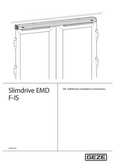
Additional installation instructions Slimdrive EMD-F-IS
Slimdrive EMD F-IS 164990-01 EN Additional installation instructions Slimdrive EMD F-IS Contents … 1 Introduction … Symbols and illustrations … Product liability … Reference documents … 2 Fundamental safety precautions … Intended use … Safety notices … 3 Product description … Areas of application … Basic structure and extension … 4 Types of installation … Use of the roller lever types depending on the type of installation … Type of installation transom installation hinge side … Type of installation transom installation opposite hinge side … Installation of the drives and IS connection of active and passive leaves … Replace brake unit on the active leaf drive … 13 … CE mark according to EN 1158 … 19 … Identification plate … 19 … Commissioning … 19 … Service and maintenance … 19 … Maintenance requirements … 19 Additional service work for Slimdrive EMD F-IS systems … 19 Troubleshooting … 19 Slimdrive EMD F-IS Introduction … Introduction … Symbols and illustrations Important information and technical notes are highlighted to explain correct operation. Symbol Meaning means “important note” Information on avoiding material damage, improved understanding or optimising the workflows means “additional Information” XX … Symbol for an action: This means you have to do something. XX If there are several actions to be taken, keep to the given order. Product liability In compliance with the liability of the manufacturer for his products as defined in the German “Product Liability Act”, compliance with the information contained in this brochure (product information and intended use, misuse, product performance, product maintenance, obligations to provide information and instructions) must be ensured. Failure to comply releases the manufacturer from his statutory liability. … Reference documents Type Installation instructions Wiring diagram Cable plan Name Slimdrive EMD / EMD-F Slimdrive EMD / EMD-F Slimdrive EMD / EMD-F These documents are subject to change. Use only the most recent version. … Fundamental safety precautions … Intended use The door closing sequence control Slimdrive EMD F-IS has been designed for automatic control during the closing of double-leaf single-action swing doors. The components required supplement the Slimdrive EMD-F drive and must be installed according to these instructions. The closing sequence control Slimdrive EMD F-IS àà is designated for use on fire and smoke protection doors. àà may be used on escape and rescue routes. àà must not be used for potentially explosive areas. Any improper use such as permanent manual operation, as well as any modification to the product, is not permitted. … Safety notices The description of the overall installation of the drive is not the subject of these instructions. This information can be found in the installation instructions Slimdrive EMD-F. All the necessary safety notices for conversion or extension to a double-leaf version can be found on the following pages. When installing the closing sequence control, the applicable standards must be observed, see the Slimdrive EMD / EMD-F installation instructions. DIN EN 1158 is also applicable … Product description Slimdrive EMD F-IS … Product description … Areas of application See installation instructions Slimdrive EMD-F for mechanical and electrical data. … Basic structure and extension … .1 Drive Slimdrive EMD F-IS – active leaf transom installation hinge side … 2 … 4 Wire rope guide Ventilation lever brake K-BS IS-brake Slimdrive EMD F-IS … .2 Product description Drive Slimdrive EMD F-IS – passive leaf transom installation hinge side … 2 … .3 Trip rocker Wire rope guide Drive Slimdrive EMD F-IS – active leaf transom installation opposite hinge side … 2 … Ventilation lever brake K-BGS Wire rope guide IS-brake … Product description … .4 Slimdrive EMD F-IS Drive Slimdrive EMD F-IS – passive leaf transom installation opposite hinge side … .5 Trip rocker Accessories … 2 … Wire rope Side panel for continuous cover Side panel for intermediate cover kit For other accessories see installation instructions Slimdrive EMD-F. … Slimdrive EMD F-IS Types of installation … Types of installation … Use of the roller lever types depending on the type of installation Also heed the marking on the roller lever. Type of installation Transom installation hinge side Transom installation opposite hinge side … Installation side DIN left DIN right DIN left Roller lever Standard Standard Door leaf DIN left DIN right Door leaf DIN right Type of installation transom installation hinge side With this type of installation, only roller guide rail and lever can be used. Details about permissible reveal depth, door overlap and installation holes can be found in the Slimdrive EMD-F installation instructions. Passive leaf … Active leaf Type of installation transom installation opposite hinge side With this type of installation, both link arms as well as roller guide rail and lever can be used. Details about permissible reveal depth, door overlap and installation holes can be found in the Slimdrive EMD-F installation instructions. Passive leaf Active leaf Door leaf installation with mechanical, integrated closing sequence control is not possible. … Types of installation … Slimdrive EMD F-IS Installation of the drives and IS connection of active and passive leaves Installation of the drives and levers see Slimdrive EMD-F installation instructions. … .1 Transom installation hinge side XX XX XX Move active leaf to open position. Fix the passive leaf with approx. 30° door angle. Hook the wire rope (2) with the spherical button in the trigger rocker (1) of the passive leaf drive. XX Lay the wire rope (2) from the passive leaf drive through the slots in the side panels and the wire rope guides (3) to the IS-brake on the active leaf drive. … Slimdrive EMD F-IS XX XX Types of installation Connect the wire rope (2) with the wire rope tightener (5) and headless pin (6) to the ventilation lever (4) so that the rope is taut but the ventilation lever is not yet deflected. Shorten the projecting wire rope to a suitable length. Note the correct wire rope setting (see “Correct wire rope setting” on page 11). … Types of installation … .2 Slimdrive EMD F-IS Transom installation opposite hinge side XX XX XX Move active leaf to open position. Fix the fixed leaf with approx. 10° door angle. Hook the wire rope (3) with the spherical button (1) in the trip rocker (2) of the passive leaf drive. XX Lay the wire rope from the passive leaf drive through the slots in the side panels and the wire rope guides (4) to the IS-brake on the active leaf drive. XX XX XX Connect the wire rope (3) with the wire rope tightener (5) and headless pin (6) to the ventilation lever (7) so that the rope is taut but the ventilation lever is not yet deflected. Tighten headless pin (hexagon socket … mm) in the wire rope tightener (5). The wire rope is attached. Shorten the projecting wire rope to a suitable length. Note the correct wire rope setting (see “Correct wire rope setting” on page 11). 10 Slimdrive EMD F-IS Types of installation Correct wire rope setting àà The rope must be slightly tensioned in the given door position, but must not actuate the ventilation lever. àà The ventilation lever must return to its starting position when opening the passive leaf and must not lock in a self-locking position. SW … XX … .3 Set the retaining action of the IS brake with the Allen screws (1). Function check Open active leaf to door angle of 90°. Open passive leaf to door angle of 30°. XX Allow passive leaf to close. From a door angle of approx. 5–10° for the passive leaf, the active leaf must start to close. XX Open the passive leaf again to approx. 30°, the active leaf then has to stop again. XX Use a suitable measuring instrument to check the retaining action of the door. XX XX Further test requirements: see national/international standards and regulations. àà See the wiring diagram Slimdrive EMD-F for the electrical connection between the active and passive leaves. XX During installation, take care that there is no cable in the range of movement of the ventilation lever. XX Make sure the cables are secured sufficiently well. 11 Types of installation … .4 Type of installation transom installation hinge side … .5 Type of installation transom installation opposite hinge side 12 Slimdrive EMD F-IS Slimdrive EMD F-IS Types of installation … Replace brake unit on the active leaf drive … .1 Drive for transom installation hinge side Loosen the wire rope attachment in the ventilation lever XX XX Loosen headless pin (1) with an Allen key SW … mm in the wire rope tightener. Remove wire rope (5) from the wire rope tightener, ventilation lever (2), wire rope guide (3) and side panel (4). Dismantle side panel and transformer XX XX XX XX Loosen … screws (3). Remove side panel (2) from transformer. Unscrew the screws (1). Remove transformer (4) and position so that the transformer's weight does not excessively pull on the connection cable. 13 Types of installation Slimdrive EMD F-IS Dismantle brake unit XX XX Loosen hex screws SW … mm (1) on the retaining plate (2). Turn retaining plate (2) to one side. XX Remove brake unit (3) with ventilation lever (4) from the motor shaft. 14 Slimdrive EMD F-IS XX XX XX XX Types of installation Loosen M4 countersunk screw (6) with Allen key SW … mm and remove ventilation lever (4) from the brake unit (3). Fit the ventilation lever (4) in the correct position with M4 countersunk screw (6) on the new brake unit. Tightening torque … Nm Insert new brake unit (3) in the correct position on the motor shaft. The label "OHS" (5) must be visible on the housing. Turn the retaining plate (2) back, tighten hex screws (1) with … Nm. For assembly of transformer and side panel, check the fastening and laying of the connection cable are secure. XX XX XX XX Assemble transformer and side panel. Tightening torque … Nm. Check wire rope for damage, replace wire rope if necessary. Thread wire rope through side panel, wire rope guide, ventilation lever and wire rope tightener. Fasten wire rope tightener to the wire rope. For setting of the wire rope and the mechanism for integrated closing sequence control, see chapter … .1. 15 Types of installation … .2 Slimdrive EMD F-IS Drive for transom installation opposite hinge side Loosen the wire rope attachment in the ventilation lever XX XX Loosen headless pin (1) with an Allen key SW … mm in the wire rope tightener. Pull wire rope (3) out of the wire rope tensioner, ventilation lever (2) and side panel. Dismantle side panel and transformer XX XX XX XX Loosen … screws (3). Remove side panel (2) from transformer. Unscrew the screws (1). Remove transformer (4) and position so that the transformer's weight does not excessively pull on the connection cable. 16 Slimdrive EMD F-IS Types of installation Dismantle brake unit XX XX Loosen hex screws SW … mm (1) on the retaining plate (2). Turn retaining plate (2) to one side. XX Remove brake unit (3) with ventilation lever (4) from the motor shaft. 17 Types of installation XX XX XX XX Loosen M4 countersunk screw (6) with Allen key SW … mm and remove ventilation lever (4) from the brake unit (3). Fit the ventilation lever (4) in the correct position with M4 countersunk screw (6) on the new brake unit. Tightening torque … Nm Insert new brake unit (3) in the correct position on the motor shaft. The label "OHS" (5) must be visible on the housing. Turn the retaining plate (2) back, tighten hex screws (1) with … Nm. Slimdrive EMD F-IS For assembly of transformer and side panel, check the fastening and laying of the connection cable are secure. XX XX XX XX 18 Assemble transformer and side panel. Tightening torque … Nm. Check wire rope for damage, replace wire rope if necessary. Thread wire rope through side panel, wire rope guide, ventilation lever and wire rope tightener. Fasten wire rope tightener to the wire rope. For setting of the wire rope and the mechanism for integrated closing sequence control, see chapter … .1. Slimdrive EMD F-IS … CE mark according to EN 1158 CE mark according to EN 1158 The Slimdrive EMD F-IS has the following classification according to EN 1158:1997 + A1:2002: XX … Affix the CE mark sticker on the inside of the cover. Identification plate See installation instructions Slimdrive EMD-F for marking and entries on the identification plate. … Commissioning See installation instructions and wiring diagram Slimdrive EMD-F for electrical connection, spring force setting and teaching process. … Service and maintenance … Maintenance requirements The maintenance work on the closing sequence control must be carried out by an expert during the maintenance cycle of the Slimdrive EMD and Slimdrive EMD-F drives. See installation instructions Slimdrive EMD-F for maintenance instructions. … Additional service work for Slimdrive EMD F-IS systems Danger of mechanical damage to IS trigger parts. XX Before dismantling or unhooking the link arms or roller lever, loosen wire cable coupling first. àà Check the condition of the wire rope for any damage to the sheathing. àà Measure the retaining action of the IS brake in the range of the waiting position of the active leaf, if necessary increase the retaining action, see “Correct wire rope setting” on page 11. The wire rope must be replaced if necessary. … Troubleshooting For troubleshooting and fault elimination see the fault table in the wiring diagram, "Fault messages" section. 19 Germany GEZE GmbH Niederlassung Süd-West Tel. +49 (0) 7152 203 594 E-Mail: leonberg.de@geze.com GEZE GmbH Niederlassung Süd-Ost Tel. +49 (0) 7152 203 6440 E-Mail: muenchen.de@geze.com GEZE GmbH Niederlassung Ost Tel. +49 (0) 7152 203 6840 E-Mail: berlin.de@geze.com GEZE GmbH Niederlassung Mitte/Luxemburg Tel. +49 (0) 7152 203 6888 E-Mail: frankfurt.de@geze.com GEZE GmbH Niederlassung West Tel. +49 (0) 7152 203 6770 E-Mail: duesseldorf.de@geze.com GEZE GmbH Niederlassung Nord Tel. +49 (0) 7152 203 6600 E-Mail: hamburg.de@geze.com GEZE Service GmbH Tel. +49 (0) 1802 923392 E-Mail: service-info.de@geze.com Austria GEZE Austria E-Mail: austria.at@geze.com www.geze.at Hungary GEZE Hungary Kft. E-Mail: office-hungary@geze.com www.geze.hu Scandinavia – Sweden GEZE Scandinavia AB E-Mail: sverige.se@geze.com www.geze.se Baltic States Lithuania / Latvia / Estonia E-Mail: baltic-states@geze.com Iberia GEZE Iberia S.R.L. E-Mail: info.es@geze.com www.geze.es Scandinavia – Norway GEZE Scandinavia AB avd. Norge E-Mail: norge.se@geze.com www.geze.no Benelux GEZE Benelux B.V. E-Mail: benelux.nl@geze.com www.geze.be www.geze.nl India GEZE India Private Ltd. E-Mail: office-india@geze.com www.geze.in Scandinavia – Denmark GEZE Danmark E-Mail: danmark.se@geze.com www.geze.dk Bulgaria GEZE Bulgaria - Trade E-Mail: office-bulgaria@geze.com www.geze.bg Italy GEZE Italia S.r.l E-Mail: italia.it@geze.com www.geze.it Singapore GEZE (Asia Pacific) Pte, Ltd. E-Mail: gezesea@geze.com.sg www.geze.com China GEZE Industries (Tianjin) Co., Ltd. E-Mail: chinasales@geze.com.cn www.geze.com.cn GEZE Engineering Roma S.r.l E-Mail: italia.it@geze.com www.geze.it South Africa GEZE South Africa (Pty) Ltd. E-Mail: info@gezesa.co.za www.geze.co.za GEZE Industries (Tianjin) Co., Ltd. Branch Office Shanghai E-Mail: chinasales@geze.com.cn www.geze.com.cn GEZE Industries (Tianjin) Co., Ltd. Branch Office Guangzhou E-Mail: chinasales@geze.com.cn www.geze.com.cn GEZE Industries (Tianjin) Co., Ltd. Branch Office Beijing E-Mail: chinasales@geze.com.cn www.geze.com.cn France GEZE France S.A.R.L. E-Mail: france.fr@geze.com www.geze.fr Korea GEZE Korea Ltd. E-Mail: info.kr@geze.com www.geze.com Poland GEZE Polska Sp.z o.o. E-Mail: geze.pl@geze.com www.geze.pl Romania GEZE Romania S.R.L. E-Mail: office-romania@geze.com www.geze.ro Russia OOO GEZE RUS E-Mail: office-russia@geze.com www.geze.ru Switzerland GEZE Schweiz AG E-Mail: schweiz.ch@geze.com www.geze.ch Turkey GEZE Kapı ve Pencere Sistemleri E-Mail: office-turkey@geze.com www.geze.com Ukraine LLC GEZE Ukraine E-Mail: office-ukraine@geze.com www.geze.ua United Arab Emirates/GCC GEZE Middle East E-Mail: gezeme@geze.com www.geze.ae United Kingdom GEZE UK Ltd. E-Mail: info.uk@geze.com www.geze.com GEZE GmbH Reinhold-Vöster-Straße 21–29 71229 Leonberg Germany Tel.: 0049 7152 203 … Fax.: 0049 7152 203 310 www.geze.com
PDF | 3 MB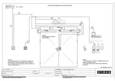
TSA 160 NT-IS 2-leaf (push.) Right hand door
PDF | 462 KB

ECturn glass guide rail opposite hinge side
DWG | 163 KB
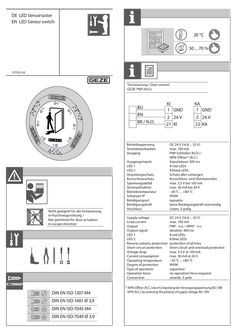
LED sensor switch
DE LED Sensortaster EN LED Sensor switch 20 °C 50 ... 70 % T 137532-02 Türsteuerung / Door control GEZE: PNP (N.O.) BU BN BK / N.O. KI … GND KA … GND … 24 V 21 KI … 24 V 23 KA Ausgangsimpuls LED … LED … Verpolungsschutz Kurzschlussschutz Spannungsabfall Stromaufnahme Betriebstemperatur Schutzart IP Betätigungsart Betätigungskraft Anschluss DC 24 V (16,8 ... 32 V) max. 100 mA PNP-Schließer (N.O.) / NPN-Öffner* (N.C.) Impulsdauer 300 ms … rote LEDs … blaue LEDs Schutz aller Leitungen Kurzschluss- und Überlastsicher max. 3,5 V bei 100 mA max. 30 mA bei 24 V –30 °C ... +80 °C IP69K kapazitiv keine Betätigungskraft notwendig Litzen, 3-polig Supply voltage Load current Output Output signal LED … LED … Reverse polarity protection Short-circuit protection Voltage drop Current consumption Operating temperature Degree of protection Type of operation Operation force Connection DC 24 V ( … ... 32 V) max. 100 mA PNP - n.o. / NPN* - n.c. duration 300 ms … red LEDs … blue LEDs protection of all lines short circuit and overload protection max. … V at 100 mA max. 30 mA at 24 V –30 °C ... +80 °C IP69K capacitive no operation force required strands, 3-pole Betriebsspannung Strombelastbarkeit Ausgang Nicht geeignet für die Ansteuerung in Fluchtwegsrichtung / Not permitted for door actuation in escape direction DIN EN ISO 1207 M4 DIN EN ISO 1481 Ø 3,9 DIN EN ISO 7045 M4 DIN EN ISO 7049 Ø 3,9 * NPN-Öffner (N.C.) durch Umpolung der Versorgungsspannung BU / BN NPN (N.C.) by reversing the polarity of supply voltage BU / BN … 200 137529 10 Ø 10 – max. 60 … 2 Ø 63 Ø 100 … 3 … 4 … 139010 139009 Ø 100 Ø 115 Ø 88 Ø 88 … 3 … 4 … 4 90° Ø 10 … 6 … 20 … Ø 10 Ø6 max. … Nm Ø6 … 2 … x 120° … Ø4 .2 Ø 10 – max. 60 Ø 76 GEZE GmbH Reinhold-Vöster-Straße 21–29 71229 Leonberg Germany Tel.: 0049 7152 203 … Fax: 0049 7152 203 310 www.geze.com
PDF | 3 MB
ECturn transom installation opposite hinge side guide rail
DOCUMENT | 6 MB
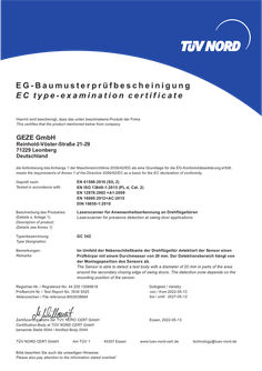
EC type examination certificate GC 342
EG-Baumusterprüfbescheinigung EC type-examination certificate Hiermit wird bescheinigt, dass das unten beschriebene Produkt der Firma This certifies that the product mentioned below from company GEZE GmbH Reinhold-Vöster-Straße 21-29 71229 Leonberg Deutschland die Anforderung des Anhangs … der Maschinenrichtlinie 2006/42/EG als eine Grundlage für die EG-Konformitätserklärung erfüllt. meets the requirements of Annex … of the Directive 2006/42/EC as a basis for the EC declaration of conformity. Geprüft nach: Tested in accordance with: EN 61508:2010 (SIL 2) EN ISO 13849-1:2015 (PL d, Cat. 2) EN 12978:2003 +A1:2009 EN 16005:2012+AC:2015 DIN 18650-1:2010 Beschreibung des Produktes: (Details s. Anlage 1) Description of product: (Details see Annex 1) Laserscanner für Anwesenheitserkennung an Drehflügeltüren Laserscanner for presence detection at swing door applications Typenbezeichnung: Type Designation: GC 342 Bemerkungen: Remarks: Im Umfeld der Nebenschließkante der Drehflügeltür detektiert der Sensor einen Prüfkörper mit einem Durchmesser von 20 mm. Der Detektionsbereich hängt von der Montageposition des Sensors ab. The Sensor is able to detect a test body with a diameter of 20 mm in parts of the area around the secondary closing edge of swing doors. The detection zone depends on the mounting position of the sensor. Registrier-Nr. / Registered No. 44 205 13089618 Prüfbericht Nr. / Test Report No. 3530 9325 Aktenzeichen / File reference 8003038664 Gültigkeit / Validity von / from 2022-05-13 bis / until 2027-05-12 Zertifizierungsstelle der TÜV NORD CERT GmbH Certification Body at TÜV NORD CERT GmbH benannte Stelle 0044 / Notified Body 0044 Essen, 2022-05-13 TÜV NORD CERT GmbH Am TÜV … 45307 Essen Bitte beachten Sie auch die umseitigen Hinweise Please also pay attention to the information stated overleaf . www.tuev-nord-cert.de technology@tuev-nord.de . . Hinweise zum TÜV NORD CERT – Zertifikat Information concerning the TÜV NORD CERT - Certificate Dieses TÜV NORD CERT - Zertifikat gilt nur für die umseitig bezeichnete Firma, das angegebene Produkt und die genannte Fertigungsstätte. Es kann nur von der Zertifizierungsstelle auf Dritte übertragen werden. This TÜV NORD CERT - certificate only applies to the. firm stated overleaf, the specified product and the manufacturing plants stated. It may only be transferred to third parties by the certification body. Notwendige Bedienungs- und Montageanweisungen Each product must be accompanied by the instructions which are necessary for its operation and installation. müssen jedem Produkt beigefügt werden. Jedes Produkt muss deutlich einen Hinweis auf den Hersteller oder Importeur und eine Typenbezeichnung tragen, damit die Identität des geprüften Baumusters mit den serienmäßig in den Verkehr gebrachten Produkten festgestellt werden kann. Each product must bear a distinct indication of the manufacturer or importer and a type designation so that the identity of the tested sample maybe determined with the product launched on the market as a standard. Der Inhaber des TÜV NORD CERT - Zertifikates ist verpflichtet, die Fertigung der Produkte laufend auf Übereinstimmung mit den Prüfbestimmungen zu überwachen und insbesondere die in den Prüfbestimmungen festgelegten oder von der Zertifizierungsstelle geforderten Kontrollprüfungen ordnungsgemäß durchzuführen. The bearer of the TÜV NORD CERT - Certificate undertakes to regularly supervise the manufacturing of products for compliance with the test specifications and in particular properly carry out the checks which are stated in the specifications or required by the test laboratory. Bei Änderungen am geprüften Produkt ist Zertifizierungsstelle umgehend zu verständigen. . die In case of modifications of the tested product the certification body must be informed immediately. Bei Änderungen und bei befristeten Zertifikaten ist das Zertifikat nach Ablauf der Gültigkeit urschriftlich an die Zertifizierungsstelle zurückzugeben. Die Zertifizierungsstelle entscheidet, ob das Zertifikat ergänzt werden kann oder ob eine erneute Zertifizierung erforderlich ist. In case of modifications and expiration of validity the original certificate must be returned to the certification body immediately. The certification body decides if the certificate can be supplemented or whether a new certification is required. Für das TÜV NORD CERT - Zertifikat gelten außer den vorgenannten Bedingungen auch alle übrigen Bestimmungen des allgemeinen Vertrages. Es hat solange Gültigkeit, wie die Regeln der Technik gelten, die der Prüfung zu Grunde gelegt worden sind, sofern es nicht auf Grund der Bedingungen des allgemeinen Vertrages früher zurückgezogen wird. In addition to the conditions stated above, all other provisions of the General Agreement are applicable to the TÜV NORD CERT - Certificate. It will be valid as long as the rules of technology on which the test was based are valid, unless revoked previously pursuant to the provisions of the General Agreement. Dieses TÜV NORD CERT - Zertifikat verliert seine Gültigkeit und muss unverzüglich der Zertifizierungsstelle zurückgegeben werden, falls es ungültig wird oder für ungültig erklärt wird. The TÜV NORD CERT - Certificate will become invalid and shall be returned to the certification body immediately in the event that it shall expire without delay when it has expired or revoked. ANLAGE ANNEX Anlage 1, Seite … von … Annex 1, page … of … zur EG-Baumusterprüfbescheinigung / to EC type-examination certificate Registrier-Nr. / Registered No. 44 205 13089618 Allgemeine Angaben: General Information: Siehe Seite … der EG-Baumusterprüfbescheinigung See also page … of the EC type-examination certificate Typenbezeichnung: Type designation: GC 342 Max. Erfassungsbereich: Max. detection range: … m (diagonal) bei einem Reflektionsgrad von … % … m (diagonal) with reflectivity of … % . Öffnungswinkel: Opening angle: Winkelauflösung: Angular resolution: Typ. min. Objektgröße: Typ. min. object size: Prüfkörper: Test body: Türflügelschutz: Door wing protection: max 90° . . Scharnierbereich: Hinge area: max 20° Türflügelschutz: Door wing protection: 1,3° . . Scharnierbereich: Hinge area: 0,2° Türflügelschutz: Door wing protection: 10 cm @ … m (in proportion to object distance) . . Scharnierbereich: Hinge area: … cm @ … m (in proportion to object distance) Türflügelschutz: Door wing protection: 700 mm x 300 mm x 200 mm (test body CA according to EN 16005/DIN 18650) . . Scharnierbereich: Hinge area: Ø20 mm x 500 mm (2% reflectance) Essen, 2022-05-13 Zertifizierungsstelle der TÜV NORD CERT GmbH Certification Body at TÜV NORD CERT GmbH benannte Stelle 0044 / Notified Body 0044 TÜV NORD CERT GmbH . Am TÜV … 45307 Essen www.tuev-nord-cert.de technology@tuev-nord.de ANLAGE ANNEX Anlage 1, Seite … von … Annex 1, page … of … zur EG-Baumusterprüfbescheinigung / to EC type-examination certificate Registrier-Nr. / Registered No. 44 205 13089618 Versorgungsspannung: Supply voltage: 12 – 24 VDC ± 15% Energieverbrauch: Power consumption: ≤2W . Reaktionszeit: Response time: Leistung: Output: Türflügelschutz: Door wing protection: max. 50 ms . . Scharnierbereich: Hinge area: max 90 ms Elektronische Relais (galvanisch . getrennt-polaritätsfrei) Electronic relays (galvanic isolation - polarity free) Max. Schaltspannung Max. switching voltage 42 V AC/DC . . Max. Schaltstrom Max. switching current 100 mA Abmessung: Dimensions: 142 mm (L) × 85 mm (D) × 23 mm (H) (mounting bracket + … mm) Schutzart: Protection degree: IP54 Temperaturbereich: Temperature range: -30°C to +60°C (if powered) Essen, 2022-05-13 Zertifizierungsstelle der TÜV NORD CERT GmbH Certification Body at TÜV NORD CERT GmbH benannte Stelle 0044 / Notified Body 0044 TÜV NORD CERT GmbH . Am TÜV … 45307 Essen www.tuev-nord-cert.de technology@tuev-nord.de ANLAGE ANNEX Anlage 1, Seite … von … Annex 1, page … of … zur EG-Baumusterprüfbescheinigung / to EC type-examination certificate Registrier-Nr. / Registered No. 44 205 13089618 Hinweis: Remark: Sicherheitskennwerte: Safety related data: Der GC 342 ist eine ESPE, die eine berührungslose Detektion von Fingern an der sekundären Schließkante (Scharnierbereich) an kraftbetätigten Drehflügeltüren ermöglicht. Eine Risikoanalyse entsprechend der Maschinenrichtlinie MD 2006/42/EG hat gezeigt, dass der GC 342 als eine geeignete Schutzeinrichtung, wie in DIN 18650-2:2010, Kapitel … . … und EN 16005:2012+AC:2015, Kapitel … . … angegeben, angesehen werden kann. Der Detektionsbereich hängt von der Installationshöhe und der Sensoreinstellung ab, wie in der Montageanleitung beschrieben. Im Falle einer hohen Wahrscheinlichkeit des Erfassens von Fingern (z.B. Kindergarten) ist eine Kombination aus ESPE und mechanischen Lösungen in Betracht zu ziehen. The GC 342 is an ESPE which provides contactless finger protection for the secondary closing edge (hinge area) on powered swing doors. A risk analysis in compliance with the Machinery Directive MD 2006/42/EC has shown that the GC 342 can be considered an appropriate protective device as indicateded in DIN 18650-2: 2010, chapter … . … and EN 16005:2012+AC:2015, chapter … . … . The detection area depends on the installation height and the adjustment of the sensor as described in the installation instructions. In case where the probability of finger entrapment is unusually high (e.g. Kindergarten), a combination of an ESPE with mechanical solutions shall be considered. EN ISO 13849-1 Kategorie / Category … HFT … MTTFD SFF 96,57 % DCavg Hoch/High (> 100 years, PFH = 2,29 -7 1/h) Mittel/Medium (95,61) PFH 7,05 -8 1/h Performance Level d SIL … Essen, 2022-05-13 Zertifizierungsstelle der TÜV NORD CERT GmbH Certification Body at TÜV NORD CERT GmbH benannte Stelle 0044 / Notified Body 0044 TÜV NORD CERT GmbH . EN 61508 Am TÜV … 45307 Essen www.tuev-nord-cert.de technology@tuev-nord.de ANLAGE ANNEX Anlage 1, Seite … von … Annex 1, page … of … zur EG-Baumusterprüfbescheinigung / to EC type-examination certificate Registrier-Nr. / Registered No. 44 205 13089618 Hinweise zur sicheren Verwendung: Notes for safe use: 1. Allen im Sicherheitsdatenblatt des Herstellers angegebenen Sicherheitshinweisen ist zum 1. Erreichen des angegebenen Sicherheits-Integritäts- und Performance Levels Folge zu leisten. 1. All safety advices given in safety manual must be followed to achieve the specified safety integrity 1. and performance level. 2. Für eine vollständige Beurteilung einer Sicherheitsfunktion müssen alle Anforderungen 1. gemäß EN ISO 13849-1 / EN 61508 auf die vollständige Sicherheitsfunktion, in der der 1. Absicherungssensor eingesetzt wird, angewendet werden. 1. For a complete functional safety assessment of a safety function, all requirements of EN ISO 13849-1 / 1. EN 61508 have to be applied to the complete safety function in which the safety sensor is used. 3. Die Gültigkeit der Bewertung ist ausschließlich für die im technischen Bericht 3530 9325 1. beschriebenen Hard- und Softwareversionen gegeben. 1. The validity of the assessment is only given for the hard- and software versions described in 1. technical report 3530 9325. Essen, 2022-05-13 Zertifizierungsstelle der TÜV NORD CERT GmbH Certification Body at TÜV NORD CERT GmbH benannte Stelle 0044 / Notified Body 0044 TÜV NORD CERT GmbH . Am TÜV … 45307 Essen www.tuev-nord-cert.de technology@tuev-nord.de
PDF | 80 KB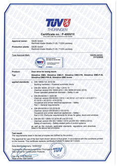
TÜV certificate P- 4005/ 10 Slimdrive EMD / Slimdrive EMD F/ Slimdrive EMD F- IS/ Slimdrive EMD Invers
PDF | 715 KB
ECturn glass guide rail opposite hinge side
DWG | 162 KB
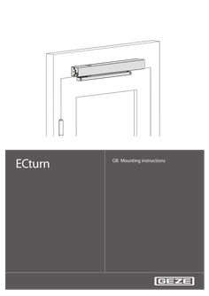
ECturn
ECturn GB Mounting instructions … ECturn Contents … 1 Symbols and means of representation … 2 Product liability … 3 Safety … Intended use … Safety instructions … Safety-conscious working … Inspection of the mounted system … Additionally applicable documents … 4 Transportation and storage … 5 Tools and aids … 6 Product description … System description and technical data … Basic structure and extension … 7 Types of mounting, stops … 8 Mounting … General information for mounting … Mounting dimensions for the types of mounting … 10 Mounting the drive … 16 Mounting the guide rail … 16 Mounting the link arm … 16 Door stop limiting … 17 Mounting and connecting the battery … 17 Mounting the door transmission cable (optional) … 18 Mounting the hood (optional) … 19 Mounting the actuation sensors … 19 Mounting the radio circuit board (optional) … 19 … Electrical connection … 19 … Mains connection … 19 10 Maintenance … 21 … Dangers during mechanical service … 21 Maintenance work … 21 Electrical servicing … 21 Electrical faults … 22 11 Disposal … 22 ECturn … Symbols and means of representation Symbols and means of representation Warnings In these instructions, warnings are used to warn against material damage and injuries. XX Always read and observe these warnings. XX Observe all the measures that are marked with the warning symbol and warning word. Warning symbol – Warning word Meaning WARNING Danger for persons. Non-compliance can result in death or serious injuries. CAUTION Danger for persons. Non-compliance can result in minor injuries. CAUTION Information on avoiding material damage, understanding a concept or optimising the processes. Further symbols and means of representation Important information and technical notes are emphasised in order to illustrate the correct operation. Symbol Meaning means "important note" means "additional information" XX … Symbol for an action: Here you have to do something. XX Observe the sequence if there are several action steps. Product liability In accordance with the liability of the manufacturer for his products as defined in the German "Produkthaftungsgesetz" (Product Liability Act), the information contained in this brochure (product information and proper use, misuse, product performance, product maintenance, obligations to provide information and instructions) is to be observed. Non-compliance releases the manufacturer from his statutory liability. … Safety … Intended use The ECturn swing door drive is designed for the automatic opening and closing of swing-door single action doors. The ECturn swing door drive is suitable: àà solely for use in dry rooms àà in entrances and interior areas of pedestrian traffic in commercial plants and public areas àà in private areas. The ECturn swing door drive àà may not be used at fire or smoke proof doors, àà may not be used for hazardous areas. Any other use than the proper use, such as permanent manual operation, as well as all changes to the product are impermissible. … Safety … ECturn Safety instructions àà The prescribed mounting, maintenance and repair work must be performed by properly trained personnel authorised by GEZE. àà The country-specific laws and regulations are to be observed during safety-related tests. àà GEZE shall not be liable for injuries or damage resulting from unauthorised modification of the system. àà GEZE shall not be liable if products from other manufacturers are used with GEZE equipment. àà Only original GEZE parts may be used for repair and maintenance work as well. àà The connection to the power supply must be made by a professional electrician. Perform the power connection and safety earth conductor test in accordance with DIN VDE 0100-610. Exception: If the ECturn swing door drive is connected to the mains voltage by the mounted power plug, the connection does not have to be carried out by a qualified electrician. àà Use a customer-accessible 10-A automatic circuit-breaker as the line-side disconnecting device. àà Observe the latest versions of guidelines, standards and country-specific regulations, in particular: àà ASR A1.7 “Doors and Gates” àà DIN 18650 "Building hardware - Powered pedestrian doors" àà VDE 0100; Part 610 "Erection of low-voltage installations" àà Accident-prevention regulations, especially BGV A1 "General regulations" and BGV A2 "Electrical systems and equipment" àà VDE 0100-610 "Erection of low-voltage installations" … Safety-conscious working àà Secure the workplace against unauthorized entry. àà Use only cables prescribed in the cable plan. Lay screening in accordance with the wiring diagram. Secure loose, internal drive cables with cable ties. àà Before working on the electrical system: àà Disconnect the drive from the 230 V mains network and check to ensure that it is deenergised. àà Disconnect the controller from the 24 V battery. àà Note that the system will still be supplied with power, despite the fact that the power supply is disconnected, if an uninterruptible power supply (UPS) is used. àà Always use insulated wire-end ferrules for wire cores. àà Attach safety labels to glass door leaves. àà Danger of injury by broken glass! àà Danger of injury by sharp edges in the drive! … Inspection of the mounted system Safety analysis (danger analysis) In accordance with Machine Directive 2006/42/EC and DIN 18650, a danger analysis must be performed and the door system identified in accordance with CE Identification Directive 98/68/EEC before commissioning the door system. This includes: àà Checking measures for security and prevention of crushing, impact, shearing or drawing-in spots. àà Checking the function of the safety and actuation sensors. àà Checking the protective conductor connection to all metal parts which can be touched. … Additionally applicable documents Drawing No. Type 70107-9-0951 ECturn wiring diagram 70107-9-0962 ECturn cable plan The diagrams are subject to change. Use only the most recent versions. … ECturn … Transportation and storage Transportation and storage Caution! Damage to the ECturn swing door drive through hard knocks and falls! XX Do not throw or let drop the ECturn. àà Store dry. Protect from moisture during transportation and storage. àà Storage temperatures under –30 °C and over + 60 °C can result in damage to the device. … Tools and aids Tool Size Tape measure – Marking pen – Set of Allen keys – Screwdriver set Slotted … mm, crosstip Side-cutting pliers – Crimping pliers for cables – Wire stripper – Multimeter – Display programme switch (Mat. No. 103940) – … Product description … System description and technical data The ECturn is a swing door drive operating fully automatically that is actuated by sensors or switches. The ECturn operates electrically during opening and closing. ���������������� ECturn field of application �������������������� Light grey Low energy Dark grey Automatic Mechanical data àà Dimensions (H x D x L): 60 mm x 60 mm x 580 mm àà Ambient temperature range: –15 °C to +50 °C àà Drive mass: approx. … kg Electrical data àà Mains connection: 110–230 V AC +10% –14%, 50/60 Hz àà Power consumption: max. 75 W àà Externally connectable devices: 24 V DC, max. 600 mA … Product description ECturn … Basic structure and extension … .1 Drive � � … 2 … 4 … .2 Controller cover Motor Gearing Battery (optional) Power connection (in the side element) … 7 … 9 Power plug Spindle cover Controller with power pack Hood (optional) Height-adjustable guide rail (±2 mm) �� �� 10 11 12 13 … Slide block Rail End piece Lever ECturn … .3 Product description Link arm For soffit depth SD: àà … 100 mm àà 90 … 200 mm … .4 Mounting plate for drives (optional) Depending on the installation situation a mounting plate is required. A mounting plate is generally recommended to facilitate mounting. … .5 Actuation elements (accessories) In accordance with the specifications in the wiring diagram, Mat. No. 134079 … Types of mounting, stops … ECturn Types of mounting, stops The opening angle of the door has to be limited by a door stop. Accessories: Door stop buffer, integrated opening restrictor (only for guide rail). The ECturn allows the following types of stop, each for doors DIN left and doors DIN right: Hinge side Transom mounting hinge side with guide rail max. soffit depth SD: 40 mm max. door overlap O: 40 mm Door panel mounting hinge side with guide rail max. door overlap O: –50…+30 mm Door panel mounting hinge side with link arm max. door overlap O: 200 mm … O Door overlap Opposite hinge side Transom mounting opposite hinge side with link arm for soffit depths SD: 0…100 mm 90…200 mm Transom mounting opposite hinge side with guide rail max. soffit depth SD: 30 mm Door panel mounting opposite hinge side with guide rail max. soffit depth SD: 20 mm SD Soffit depth ECturn Mounting … Mounting … General information for mounting àà Observe all the instructions. Incorrect mounting can result in serious injuries. àà Observe the specified ambient temperature range at the installation location of the drive. àà After completing mounting check the settings and functionality of the drive! … .1 Scope of delivery and completeness XX Open all the packaging units. Check whether they are complete and familiarise yourself with the parts. ECturn door drive with guide rail or link arm àà Drive unit àà … drive àà … set of fastening screws Depending on order: àà Slide rail àà … rail àà … lever àà … set of fastening screws or àà Link arm (size depending on soffit depth) àà … set of fastening screws àà Accessories (optional) àà Hood àà Actuation elements: in accordance with the specifications in the wiring diagram àà Door stop buffer àà Mounting plate(s) with a set of fastening screws àà Battery àà Radio circuit board DCU702 àà Door transmission cable … .2 Preparations to be made by the customer Checking of the location conditions and the required physical conditions WARNING! Danger of injury through falling components! Unsecured components may fall down when under load. XX When mounting the ECturn swing door drive ensure that the substructure ensures safe fastening of the drive. XX Use suitable means of fastening such as anchors, rivet nuts, etc. XX XX XX XX Before mounting the drive check whether the door leaf is in a good mechanical state and can be opened and closed easily. Mount the bottom edge of the element mounted at the lowest point (guide rail or link arm) at least … m above the floor. Lay cables in accordance with the cable plan. Check the planned type of stop on the leaf or frame profile (see Chapter 7). … Mounting ECturn … Mounting dimensions for the types of mounting … .1 Transom mounting hinge side with guide rail Fixing with mounting plate ��� �� ��� ��� ��� ��� ��� �� ��� ��� �� �� ��� ��� ����� ��� ����� ��� �� ����� �� 14 15 16 ��� �� �� ��� �� �� Direct fixing ����� �� �� �� Dimensional reference hinge middle Cable entry for power supply cable Cable entry for control cables XX Observe drilling template: DIN left and DIN right mirrored. Fastening means àà Mounting plate M5 àà Base plate M5 or chip board screws àà Guide rail M5 or chip board screws XX Take drive orientation into account: Motor towards hinge. Required space 17 18 19 10 ECturn required space Dimensional reference top edge door profile = Top edge guide rail Required space for guide rail ECturn … .2 Mounting Transom mounting opposite hinge side with guide rail Fixing with mounting plate Direct fixing 575 633 415 … 16 266 302 Ø16 70 … 70 … 15 15 14 14 15 16 131 78 16 Ø16 Ø16 142 78 14 Dimensional reference hinge middle Cable entry for power supply cable Cable entry for control cables X Observe drilling template: DIN left and DIN right mirrored. Fastening means à Mounting plate M5 à Base plate M5 or chip board screws à Guide rail M5 or chip board screws X Take drive orientation into account: Motor towards hinge. Required space 17 19 20 ECturn required space Required space for guide rail Dimensional reference bottom edge frame (lintel) 11 Mounting … .3 ECturn Transom mounting opposite hinge side with link arm Fixing with mounting plate Direct fixing �� �� 14 15 16 21 �� �� �� �� �� �� Dimensional reference hinge middle Cable entry for power supply cable Cable entry for control cables For mounting dimensions of the link arm refer to the "ECturn link arm mounting instructions" (134590) XX Observe drilling template: DIN left and DIN right mirrored. Fastening means àà Mounting plate M5 àà Base plate M5 or chip board screws XX Take drive orientation into account: Motor towards hinge. Required space 17 20 22 12 ECturn required space Dimensional reference bottom edge frame (lintel) Space required link arm ECturn … .4 Mounting Door panel mounting hinge side with link arm Fixing with mounting plate Direct fixing �� �� 14 15 16 21 �� �� �� �� �� �� Dimensional reference hinge middle Cable entry for power supply cable Cable entry for control cables For mounting dimensions of the link arm refer to the "ECturn link arm mounting instructions" (134590) XX Observe drilling template: DIN left and DIN right mirrored. Fastening means àà Mounting plate M5 àà Base plate M5 or chip board screws XX Take drive orientation into account: Motor towards hinge. Required space 17 18 22 ECturn required space Dimensional reference top edge door profile Space required link arm 13 Mounting Door panel mounting hinge side with guide rail Fixing with mounting plate Direct fixing �� ����� ����� �� �� ��� ����� �� ��� �� �� �� �� ��� ����� ��� ��� ��� ��� ��� ��� ��� 14 15 16 ��� ��� �� �� �� �� ��� … .5 ECturn �� �� Dimensional reference hinge middle Cable entry for power supply cable Cable entry for control cables XX Observe drilling template: DIN left and DIN right mirrored. Fastening means àà Mounting plate M5 àà Base plate M5 or chip board screws àà Guide rail M5 or chip board screws XX Take drive orientation into account: Motor towards hinge. Required space 17 18 19 14 ECturn required space Dimensional reference top edge door profile Required space for guide rail ECturn … .6 Mounting Door panel mounting opposite hinge side with guide rail Fixing with mounting plate �� Direct fixing �� �� �� ��� ����� ��� �� �� ��� ��� ��� ��� ����� ����� ��� ��� ��� 14 15 16 ��� ��� ����� �� �� Dimensional reference hinge middle Cable entry for power supply cable Cable entry for control cables XX Observe drilling template: DIN left and DIN right mirrored. Fastening means àà Mounting plate M5 àà Base plate M5 or chip board screws àà Guide rail M5 or chip board screws XX Take drive orientation into account: Motor towards hinge. Required space 17 19 20 ECturn required space Required space for guide rail Dimensional reference bottom edge frame (lintel) 15 Mounting … ECturn Mounting the drive XX During mounting ensure that the connection cables are not pinched. XX XX Pull the hood off. If necessary, screw on the mounting plate. Screw on the drive. For positioning refer to the top view in the drawings of Chapter … . Break out the plastic part in the hood for the spindle. Mount the spindle cover. Fill in the information plate and stick it clearly visible onto the drive unit. Attach the hood. XX Use the supplied M5 screws or chip board screws. XX XX XX XX XX … Mounting the guide rail … .1 Mounting the lever XX … .2 In order to mount the lever use only the supplied hexagon socket-head screw with coating in the lower thread section! Mounting the guide rail XX Observe the mounting instructions for the guide rail. The slide block can be clipped out of the lever for dismantling. Transom mounting guide rail Door panel mounting guide rail �� �� XX … Mounting the link arm XX 16 Screw in the hexagon socket-head screw (23) and tighten it (tightening torque 15 Nm). Observe the mounting instructions in the link arm packaging. ECturn … Mounting Door stop limiting XX When mounting the door panel take care of the pinch and shearing points of the door edges when laying the cables! XX Use the guide rail only with and integrated buffer or use a stop buffer on the floor. XX Use the link arm only with a stop buffer on the floor. XX Check the physical conditions. Open and close the door manually. Mount the stop buffer (24) on the floor. XX XX �� … Mounting and connecting the battery XX Screw on the battery (4) using … screws (25). �� � XX Plug the plug (26) into the slot. �� 17 Mounting … ECturn Mounting the door transmission cable (optional) XX XX XX Loosen bolts (27). Remove the cover (28) for the side element. Break out the breaking point (29) in the cover (28). �� �� �� �� XX XX XX �� Unscrew the nut (31) at the door transmission cable (30). Thread the door transmission cable (30) through the cover (28). Screw the nut (31) tight in the cover (28). �� �� XX XX XX XX Loosen the strain relief (33). Loosen the screw (34) and pull off the protective conductor. Loosen the cable at the terminal strip (35). Remove the power plug (32) with cable. �� �� �� �� 18 ECturn Electrical connection XX XX XX XX … Connect the door transmission cable in the terminal strip (35) in accordance with the wiring diagram. Connect the protective conductor and secure with screw (34). Place on the cover (28) for the side element. Tighten screws (27). Mounting the hood (optional) XX During mounting ensure that cables are not pinched. XX Slide the hood (36) over the ECturn until it latches in audibly. Take the position of the drive axle of the motorgearing unit into account. �� … Mounting the actuation sensors Sensors mounted on the wall or ceiling have to be positioned so that the door does not move through the field of detection of the sensor during opening and closing since self-actuation is otherwise possible. For electrical connections, see the wiring diagram. … Mounting the radio circuit board (optional) XX Observe the mounting instructions in the packaging of the radio circuit board DCU702. … Electrical connection … Mains connection The ECturn swing door drive is provided with a power plug in the factory. If there are cables provided by the customer and connection is not carried out with the power plug, the power connection has to be carried out by a qualified electrician. WARNING! Danger of fatal injury through electric shock when connecting the ECturn swing door drive without a power plug. XX The electrical system (230 V) may only be connected by a qualified electrician! Observe the VDE regulations. XX Use suitable means of fastening such as anchors, rivet nuts, etc. 19 Electrical connection ECturn When mounting the door panel take care of the pinch and shearing points of the door edges when laying the cables! XX Before working on the electrical system, disconnect the system from the mains network. XX If it exists, unplug the battery. àà In accordance with the valid regulations it must be possible to deenergize the door drive at a suitable point. XX In the case of a fixed connection by the customer, provide an all-pole disconnecting device. XX If flexible cables are used, always use insulated wire-end ferrules. XX XX Plug in the power plug (32). If there are cables provided by the customer and connection is not carried out with the power plug: �� �� �� �� XX XX �� Loosen bolts (27). Remove the cover (28) for the side element. �� �� �� �� XX XX XX XX XX XX Loosen the strain relief (33). Loosen the screw (34) and pull off the protective conductor. Loosen the cable at the terminal strip (35). Remove the power plug (32) with cable. Connect the 230 V power cable in the terminal strip (35) in accordance with the wiring diagram. Connect the protective conductor and secure with screw (34). The sheath of the power supply cable must be laid to the strain relief (33). XX XX XX 20 Tighten the strain relief (33). Place on the cover (28) for the side element. Tighten screws (27). ECturn 10 Maintenance Maintenance The following prescribed maintenance work at the ECturn must be carried out at least once a year by properly trained personnel. … Dangers during mechanical service WARNING! Danger of fatal injury via electric shock! XX Disconnect the power supply from the drive by a disconnecting device supplied by the customer and secure it against reactivating. WARNING! Danger of injury through crushing! XX When working on the drive ensure that you cannot be injured by swing movements of the lever or of the link arm. WARNING! Danger of getting burnt through hot motor! The motor in the drive can have relatively high temperatures after continuous operation or poor ease of movement or other defects. XX If necessary, switch off the power supply and first let the motor cool down before carrying out work. … Maintenance work The ECturn is free of maintenance to a great extent. The following work has to be carried out during maintenance: XX Inspect fastening screws for firm seating. XX Tighten the fastening screw for the link arm or roller lever. XX Clean the inside of the roller guide rail. XX Check that the door latch functions correctly and is clean, oil lightly if necessary. XX Check the roller lever or the link arm for damage, replace if necessary. Carrying out a manual trial run Requirements: The drive has been disconnected at all poles from the power supply. XX XX XX Ensure that the door moves properly. Check that the mounting is correct. Switch the power supply back on or plug the power plug back on. … Electrical servicing àà Keep the test documents up-to-date and make them available. àà With DPS: In the menu item sa query àà the number of openings ( co), àà the operating hours ( ho) and àà service (so) and document them in the maintenance manual. àà After completing the maintenance work, always execute the Learning function for the ECturn (see Section … ). àà Check the functioning of the actuating and presence sensors and replace if necessary. àà Direct querying of the controller using S1, S2: àà Refer to the wiring diagram, Commissioning and servicing chapter as well as Parameter menu service LEDs and display programme switch chapter. 21 Disposal ECturn … Electrical faults Fault messages are stored and can be displayed on the display programme switch. If a fault is currently active, it is shown every 10 seconds on the display programme switch. If the dot lights up in the left half of the display programme switch, the system was unable to completely initialise after being switched on. Either there is an obstruction or something in the system itself has become jammed. The dot extinguishes as soon as the door has been opened completely and closed again once. For troubleshooting and elimination: see fault table in the wiring diagram, "Fault messages" section. 11 Disposal XX 22 When disposing of the door system, separate the different materials and have them recycled. ECturn 23 Germany GEZE Sonderkonstruktionen GmbH Planken … 97944 Boxberg-Schweigern Tel. +49 (0) 7930-9294-0 Fax +49 (0) 7930-9294-10 E-Mail: sk.de@geze.com Germany GEZE GmbH Niederlassung Nord/Ost Bühringstraße … 13086 Berlin (Weissensee) Tel. +49 (0) 30-47 89 90-0 Fax +49 (0) 30-47 89 90-17 E-Mail: berlin.de@geze.com Germany GEZE GmbH Niederlassung West Nordsternstraße 65 45329 Essen Tel. +49 (0) 201-83082-0 Fax +49 (0) 201-83082-20 E-Mail: essen.de@geze.com Germany GEZE GmbH Niederlassung Mitte Adenauerallee … 61440 Oberursel (b. Frankfurt) Tel. +49 (0) 6171-63610-0 Fax +49 (0) 6171-63610-1 E-Mail: frankfurt.de@geze.com Germany GEZE GmbH Niederlassung Süd Breitwiesenstraße … 71229 Leonberg Tel. +49 (0) 7152-203-594 Fax +49 (0) 7152-203-438 E-Mail: leonberg.de@geze.com Germany GEZE Service GmbH Reinhold-Vöster-Straße 25 71229 Leonberg Tel. +49 (0) 7152-9233-0 Fax +49 (0) 7152-9233-60 E-Mail: service-info.de@geze.com Germany GEZE Service GmbH Niederlassung Berlin Bühringstraße … 13086 Berlin (Weissensee) Tel. +49 (0) 30-470217-30 Fax +49 (0) 30-470217-33 E-Mail: service-info.de@geze.com Austria GEZE Austria GmbH Wiener Bundesstrasse 85 5300 Hallwang b. Salzburg Tel. +43-(0)662-663142 Fax +43-(0)662-663142-15 E-Mail: austria.at@geze.com Baltic States GEZE GmbH Baltic States office Dzelzavas iela 120 S 1021 Riga Tel. +371 (0) 67 89 60 35 Fax +371 (0) 67 89 60 36 E-Mail: office-latvia@geze.com GEZE GmbH P.O.Box 1363 Reinhold-Vöster-Straße 21–29 71229 Leonberg Germany Benelux GEZE Benelux B.V. Leemkuil … Industrieterrein Kapelbeemd 5626 EA Eindhoven Tel. +31-(0)40-26290-80 Fax +31-(0)40-26 290-85 E-Mail: benelux.nl@geze.com Bulgaria GEZE Bulgaria - Trade Representative Office 61 Pirinski Prohod, entrance „B“, 4th floor, office 5, 1680 Sofia Tel. +359 (0) 24 70 43 73 Fax +359 (0) 24 70 62 62 E-Mail: office-bulgaria@geze.com China GEZE Industries (Tianjin) Co., Ltd. Shuangchenzhong Road Beichen Economic Development Area (BEDA) Tianjin 300400, P.R. China Tel. +86(0)22-26973995-0 Fax +86(0)22-26972702 E-Mail: Sales-info@geze.com.cn China GEZE Industries (Tianjin) Co., Ltd. Branch Office Shanghai Unit 25N, Cross Region Plaza No. 899, Ling Ling Road, XuHui District 200030 Shanghai, P.R. China Tel. +86 (0)21-523 40 960 Fax +86 (0)21-644 72 007 E-Mail: chinasales@geze.com.cn China GEZE Industries (Tianjin) Co., Ltd. Branch Office Guangzhou Room 17C3 Everbright Bank Building, No.689 Tian He Bei Road 510630 Guangzhou, P.R. China Tel. +86(0)20-38731842 Fax +86(0)20-38731834 E-Mail: chinasales@geze.com.cn China GEZE Industries (Tianjin) Co., Ltd. Branch Office Beijing Room 1001, Tower D Sanlitun SOHO No. 8, Gongti North Road, Chaoyang District, 100027 Beijing, P.R.China Tel. +86-(0)10-5935 9300 Fax +86-(0)10-5935 9322 E-Mail: chinasales@geze.com.cn China GEZE Industries (Tianjin) Co., Ltd. Branch Office Singapore 21, Bukit Batok Crescent, No. 23-75, Wcega Tower, Singapore 658065 Tel. +65-6846 1338 Fax +65-6846 9353 E-Mail: gezesea@geze.com.sg France GEZE France S.A.R.L. ZAC de l’Orme Rond RN 19 77170 Servon Tel. +33-(0)1-606260-70 Fax +33-(0)1-606260-71 E-Mail: france.fr@geze.com Tel.: 0049 7152 203-0 Fax: 0049 7152 203-310 www.geze.com Hungary GEZE Hungary Kft. Bartók Béla út 105-113. Budapest H-1115 Tel. +36 (1) 481 4670 Fax +36 (1) 481 4671 E-Mail: office-hungary@geze.com Iberia GEZE Iberia S.R.L. Pol. Ind. El Pla C/Comerc, 2-22, Nave 12 08980 Sant Feliu de Llobregat (Barcelona) Tel. +34 9-02 19 40 36 Fax +34 9-02 19 40 35 E-Mail: info@geze.es India GEZE India Private Ltd. MF2 & 3, Guindy Industrial Estate Ekkattuthangal Chennai - 600 097 Tamilnadu Tel. +91 (0) 44 30 61 69 00 Fax +91 (0) 44 30 61 69 01 E-Mail: office-india@geze.com Italy GEZE Italia Srl Via Giotto, … 20040 Cambiago (MI) Tel. +3902950695-11 Fax +3902950695-33 E-Mail: italia.it@geze.com Italy GEZE Engineering Roma Srl Via Lucrezia Romana, 91 00178 Roma Tel. +3906-7265311 Fax +3906-72653136 E-Mail: roma@geze.biz Kazakhstan GEZE Central Asia 050061, Almaty, Kasakhstan Rayimbek ave. 348, A, office 310 Tel. +7 (0) 72 72 44 78 03 Fax +7 (0) 72 72 44 78 03 E-Mail: office-kazakhstan@geze.com Poland GEZE Polska Sp.z o.o. ul. Annopol 21 03-236 Warszawa Tel. +48 (0)22 440 … 440 Fax +48 (0)22 440 … 400 E-Mail: geze.pl@geze.com Romania GEZE Romania S.R.L. IRIDE Business Park Building nr. 10, level … Str. Dimitrie Pompei nr. 9–9a RO-020335 Bucharest, sector … Tel. +40 (0) 316 201 257 Fax +40 (0) 316 201 258 E-Mail: office-romania@geze.com Russian Federation GEZE GmbH Representative Office Russia Gamsonovskiy Per. … 115191 Moskau Tel. +7 (0) 495 933 06 59 Fax +7 (0) 495 933 06 74 E-Mail: office-russia@geze.com Scandinavia GEZE Scandinavia AB Mallslingan 10 Box 7060 18711 Täby, Sweden Tel. +46(0)8-7323-400 Fax +46(0)8-7323-499 E-Mail: sverige.se@geze.com 135859-02 Scandinavia GEZE Norway Industriveien 34 B 2072 Dal Tel. +47(0)639-57200 Fax +47(0)639-57173 E-Mail: norge.se@geze.com Scandinavia GEZE Finland Postbox 20 15871 Hollola Tel. +358(0)10-4005100 Fax +358(0)10-4005120 E-Mail: finland.se@geze.com Scandinavia GEZE Denmark Mårkærvej 13 J-K 2630 Taastrup Tel. +45(0)46-323324 Fax +45(0)46-323326 E-Mail: danmark.se@geze.com South Africa DCLSA Distributors (Pty.) Ltd. 118 Richards Drive, Midrand, Halfway House Ext. 111 P.O. Box 7934 Midrand 1685 Tel. +27(0)113158286 Fax +27(0)113158261 E-Mail: info@dclsa.co.za Switzerland GEZE Schweiz AG Bodenackerstrasse 79 4657 Dulliken Tel. +41-(0)62-2855400 Fax +41-(0)62-2855401 E-Mail: schweiz.ch@geze.com Turkey GEZE GmbH Türkiye - İstanbul İrtibat Bürosu Ataşehir Bulvarı, Ata 2/3 Plaza Kat: … D: 84 Ataşehir Kadıköy / İstanbul Tel. + 90 (0) 21 64 55 43 15 Fax + 90 (0) 21 64 55 82 15 E-Mail: office-turkey@geze.com Ukraine Repräsentanz GEZE Ukraine TOV ul. Viskoznaya, 17, building 93-B, office 12 02094 Kiev Tel. +38 (0) 44 501 22 25 Fax +38 (0) 44 499 77 25 E-Mail: office-ukraine@geze.com United Arab Emirates/GCC GEZE Middle East P.O. Box 17903 Jebel Ali Free Zone Dubai Tel. +971(0)4-8833112 Fax +971(0)4-8833240 E-Mail: geze@emirates.net.ae United Kingdom GEZE UK Ltd. Blenheim Way Fradley Park Lichfield Staffordshire WS13 8SY Tel. +44(0)1543443000 Fax +44(0)1543443001 E-Mail: info.uk@geze.com
PDF | 3 MB
Perlan AUT-NT
GEZE Perlan AUT-NT GB Wiring diagram … GEZE Perlan AUT-NT Table of contents … 1 Symbols and means of representation … Warnings … Further symbols and means of representation … 2 Validity … 3 Product liability … 4 Notes … Important safety instructions … Mounting instructions … Safety-conscious working … Checking the mounted system … Disposing of the door system … 5 Abbreviations … 6 Supply terminals … 7 Function description … 8 Mounting of the components … Requirement … Mounting the flush-mounted controller and power pack … 9 Contactors … 10 … Radar movement detector GC 302 R … 10 Switch (floating contact) … 11 Radio control … 12 10 Contactor close … 12 … Switch (floating contact) … 12 Radio control … 12 11 Push & Go … 12 12 Stop … 12 13 Operating mode … 13 … Setting the operating mode … 13 Operating modes … 13 Display of the operating mode … 13 Behaviour in the individual operating modes … 14 14 Mains connection … 15 … Safety instructions … 15 15 Motor … 15 16 Low-energy operation … 15 17 Commissioning and service … 16 … Configuration … 17 Steps for commissioning … 18 18 Error display … 19 GEZE Perlan AUT-NT Symbols and means of representation … Symbols and means of representation … Warnings In these instructions, warnings are used to warn against material damage and injuries. XX Always read and observe these warnings. XX Observe all the measures that are marked with the warning symbol and warning word. Warning symbol – … Warning word Meaning DANGER Danger for persons. Non-compliance will result in death or serious injuries. WARNING Danger for persons. Non-compliance can result in death or serious injuries. CAUTION Danger for persons. Non-compliance can result in minor injuries. CAUTION Information on avoiding material damage, understanding a concept or optimising the processes. Further symbols and means of representation Important information and technical notes are emphasised in order to illustrate the correct operation. Symbol Meaning means "important note" means "additional information" XX … Symbol for an action: Here you have to do something. XX Observe the sequence if there are several action steps. Validity Valid for units from: àà Hardware: Perlan AUT-NT, Rev. F àà Software: Perlan AUT-NT, V … Product liability In accordance with the liability of manufacturers for their products as defined in the German "Produkthaftungsgesetz" (Product Liability Act), the information contained in these instructions (product information and proper use, misuse, product performance, product maintenance, obligations to provide information and instructions) is to be observed. Non-compliance releases the manufacturer from its statutory liability. … Notes … Important safety instructions To ensure personal safety, it is important to follow these instructions. Keep these instructions. àà Only qualified personnel who are authorised by GEZE may carry out mounting, commissioning and maintenance. àà GEZE shall not be liable for injuries or damage resulting from unauthorised modification of the equipment. àà GEZE shall not be liable if products from other manufacturers are used with GEZE equipment. Use only original GEZE parts for repair and maintenance work as well. àà The connection to the power supply must be carried out by a qualified electrician in accordance with VDE 0100 Part 610. àà The electrical installation at the customer has to have an all-pole power disconnector that can be secured reliably against reactivating (e.g. lockable switch with at least … mm contact opening). àà A customer-side 10 A overload cut-out must be used as the line-side disconnecting device. … Notes GEZE Perlan AUT-NT àà In accordance with Machinery Directive 2006/42/EC, a safety analysis must be performed and the door system identified in accordance with CE Identification Directive 93/68/EEC before the door system is commissioned. XX Enter the classification in accordance with DIN 18650-1 on the information plate and adhere the information plate onto the drive housing so that it is visible from below. XX Observe the latest versions of guidelines, standards and country-specific regulations, in particular: àà BGR 232 "Guidelines for power-operated windows, doors and gates" àà DIN 18650, Part … and Part … "Automatic door systems" àà DIN VDE 100-600 "Installation of low-voltage systems - Part … Tests" àà DIN EN 60335-1 "Safety of electrical devices for home use and similar purposes" àà Accident-prevention regulations, especially BGV A1 (VBG1) "General regulations", BGV A3 (VBG4) "Electrical systems and equipment" … Mounting instructions XX Observe the maximum permissible total current draw at the power pack for the drive unit for powering the peripherals (max. 50 mA). The sliding door drive is designed solely for use in dry rooms. XX Use only cables specified in the cable plan. XX Always use insulated wire-end ferrules for wire cores. XX Insulate unused wires. XX Secure loose, internal drive cables with cable ties. … Safety-conscious working DANGER! Danger of death from electric shock! XX Before working on the electrical system, interrupt the power supply (mains) and check the safe isolation from supply. Note that the system will still be supplied with power, despite the fact that the power supply is disconnected, if an uninterruptible power supply (UPS) is used. XX XX àà àà àà àà … Checking the mounted system XX XX … Secure the workplace against unauthorised entry. Take the swinging area of long system parts into account. Risk of injury when a sliding door drive is opened through moving parts (drawing in of hair, clothing …). Risk of injury by crushing, impact, shearing or drawing-in spots. Danger of injury by sharp edges in the sliding door drive. Risk of injury through breakage of glass. Check the measures for securing and avoiding trapping, knocking, shearing and hair etc. being drawn in. Check the function of the contactors. Disposing of the door system The sliding door drive consists of materials that should be recycled. The individual components have to be sorted in accordance with their material type: àà Metal (carrier plate, hanger bolt, …) àà Aluminium (track, cover, …) àà Plastic (roller carriage, …) àà Electronic components (controller, switch, …) àà Cables The parts can be disposed of at the local recycling station or a scrap processing company. … GEZE Perlan AUT-NT … Abbreviations Abbreviations Wire colours BN brown BK black BU blue GN GY YE green grey yellow OG PK RD orange pink red TQ turquois VT violet WH white Connections, terminals and plugs GND INC K KS … Reference potential Rotary transducer Contactor Contactor close MA MB STOP Motor Motor Stop Supply terminals CAUTION! Destruction of the component through incorrect connection. Defective controller XX Ensure that the polarity of Connections … and … is correct. Motor connection Terminal Signal name Wire colour … Earth white 85 Signal … yellow 86 Signal … green 82 +5 V brown MB Motor + red MA Motor – blue Voltage connection Terminal Signal name … Earth (–) power pack … 24 V DC (+) power pack K … 21 GND K KS … 29 GND KS STOPP … GND 15 STOPP Switch connection Terminal Signal name … 29 CLOSE 21 OPEN 15 STOP … Earth Function description The system is an electrical sliding door drive. The controller drives a 24 V DC motor that moves a linear sliding door via a toothed belt. The controller and power packs have to be mounted in separate concealed/surface-mounted boxes in accordance with DIN 49073. The housing is hidden completely in separate concealed/surface-mounted boxes. The controller is operated via a detachable switch that fits into a common switch range with a rocker switch dimension of 55 mm. The controller is supplied by a power pack. The power pack supplies 24 V direct current and is connected to Terminals … and 2. It can be mounted in a neighbouring concealed/surface-mounted box or further away. The screw terminals for connecting the lines are combined into groups: àà Supply voltage (Terminals … and 2) àà Inputs (Terminals 1, 15, 21, 29) àà Motor (Terminals MA and MB) àà Rotary transducer (Terminals 1, 85, 86 and 82) … Mounting of the components GEZE Perlan AUT-NT The hold-open time of the sliding door drive can be set via the potentiometer P1. The exact functionality of the sliding door drive can be selected by means of the DIP switch. After correct connection and commissioning the controller is ready for use. The motor is driven by pressing the buttons OPEN and CLOSE of the switch or by electrical switching of an input (Terminals 1, 15, 21, 29). … Mounting of the components Lay the conductors so that single-insulation power conductors do not cross single-insulation 24 V low voltage conductors. If conductor crossing cannot be avoided, the individual conductors have to be insulated additionally with shrink tubing. … 2 … 4 Flush-mounted box to DIN 49073 (provided by customer) Controller, Mat. No. 139993 Power pack 230 V / 24 V, Mat. No. 139994 2-fold cover frame for vertical installation … 6 Switch, Mat. No. 140101 Cover In addition to the connection displayed here, the following variants exist: àà Connection variants for controller Perlan AUT-NT àà Controller at the door in flush-mounted box àà Controller at the door in surface-mounted box àà Controller installed externally (e.g. wall recess, control cabinet …) àà Connection variants for power pack Perlan AUT-NT àà Power pack at the door in flush-mounted box àà Power pack at the door in surface-mounted box àà Power pack installed externally (e.g. wall recess, control cabinet …) … GEZE Perlan AUT-NT … Mounting of the components Requirement àà Cable laying to GEZE cable plan àà Mounting height for controller: from 850 mm to maximum 1200 mm above the top edge of the completed flooring … Mounting the flush-mounted controller and power pack The instructions describe the mounting recommended by GEZE of a connection variant with flush-mounted controller and power pack. XX Lay the 24-V output cable of the power pack into the flush-mounted box (1). … XX Connect the 24-V output cable of the power pack to the controller (2) in accordance with the wiring diagram. … 7 Mounting of the components XX GEZE Perlan AUT-NT Insert the power pack (3) into the flush-mounted box (1). … 1 XX Connect the power supply cable to the fusing terminal strip (7) of the power input line of the power pack. … 8 GEZE Perlan AUT-NT XX Mounting of the components Connect the motor connection cable to the controller (2) in accordance with the wiring diagram. … XX Mount the controller (2) in the flush-mounted box (1). … 2 … Contactors XX XX XX XX GEZE Perlan AUT-NT Fasten the controller (2) in the flush-mounted box (1) with screws. Mount the 2-fold cover frame (4) for vertical installation. Mount the cover (6) onto the 2-fold cover frame (4). Put the switch (5) onto the controller (2). … 1 … 5 … Accessories programme switches GEZE: àà Frame 1-fold, Alpine white, flush-mounted, Mat. No. 115376 àà Frame 2-fold, Alpine white, flush-mounted, Mat. No. 115377 àà Frame 3-fold, Alpine white, flush-mounted, Mat. No. 115378 àà Cover, AS500, Mat. No. 118480 àà Surface-mounted box 1-fold, Alpine white, Mat. No. 120503 àà Surface-mounted box 2-fold with AS500 cover, Alpine white, Mat. No. 128609 àà Surface-mounted box 3-fold with AS500 cover, Alpine white, Mat. No. 133206 … Contactors … Radar movement detector GC 302 R àà An additional power pack 230 V / 24 V Perlan AUT-NT is required to supply external actuation elements. XX Take the maximum permissible current draw into account when an additional power pack is used (500 mA). Wiring instructions: XX Lay the conductors so that single-insulation power conductors do not cross single-insulation 24 V low voltage conductors. XX If necessary, insulate the power and low-voltage conductors additionally with shrink tubing. àà When the contactor is actuated, the contact is closed (0 V applied to the Input 21). 10 GEZE Perlan AUT-NT Follow mounting instructions, Mat. No. 123457. àà Accessories: àà Remote control, Mat. No. 099575 àà Ceiling installation kit, Mat. No. 115384 àà Rain cover, Mat. No. 115339 L N … T 2A àà GC 302 R black, Mat. No. 124087 àà GC 302 R as per RAL, Mat. No. 124088 remote control does not work with detector hood mounted, LED not visible àà GC 302 R is a direction-sensitive radar movement detector. Contactors … BU BN XX L N 230V / 50 Hz … NT +24V … 2 … 4 … Power supply cable 230 V / 50 Hz Mains fuse 10 A by customer, with all-pole disconnection Fuse terminal strip … mm² with glass fuse 5×20 mm, T2A Power pack 230 V / 24 V, Perlan AUT-NT, Mat. No. 139994 Conductor terminal strip, 2-pole, … mm² Controller 0V … BK RD GC 302 R 50 mA +UB … -UB … 3 … WH BK BN BU … K … GND 21 K … XX XX XX … Set the detection field and sensitivity of the radar movement detector. To align the detection field, turn the planar antenna and adjust its tilt angle. If several GC302 R units are mounted next to or after one another, set different device addresses using the two DIP switches. Otherwise, the settings of the other detectors will also changed by the remote control. Switch (floating contact) àà Plastic elbow switch, white, Mat. No. 114078 àà Plastic elbow switch, stainless steel, Mat. No. 114077 àà Accessories: àà IP65 switching insert, Mat. No. 114156 àà Additional contact, Mat. No. 114157 àà Back panel for plastic elbow switch white, Mat. No. 131219, stainless steel, Mat. No. 131220 àà Stainless steel elbow switch, Mat. No. 119898 àà Stainless steel elbow switch LS990, surfacemounted, Mat. No. 128582 àà Stainless steel elbow switch LS990, flush-mounted, Mat. No. 128583 K … GND 21 K 11 Contactor close … GEZE Perlan AUT-NT Radio control XX Observe the mounting and service instructions of the GEZE Automatic Radio Program, Mat. No. 132159. WTM YE GN BN àà Radio transmitter module WTM, Mat. No. 131212 àà Hand-held radio transmitter WTH-1, Mat. No. 131209 àà Hand-held radio transmitter WTH-2, Mat. No. 131210 àà Hand-held radio transmitter WTH-4, Mat. No. 131211 àà Radio receiver module WRM-24, Mat. No. 131213 … WRM-24 … 1 … 10 G ND 24V … 24V … G ND … 2 24V … G ND … 1 G ND OUT … 15 STOPP OUT … 21 K A 29 KS 24 V output cable additional power pack Contactor KS, K, STOP B Contactor close When the Contactor close is actuated, the contact is closed (0 V applied to the Input 29). … Switch (floating contact) See Switch contactor KS … GND 29 KS … Radio control See Radio control contactor 11 Push & Go WARNING! Danger of injury through crushing! àà The Push & Go function allows actuating of the sliding door drive without contactors being used. àà When the Push & Go function is set, the sliding door drive opens the door automatically as soon as the door leaf is moved manually out of the closed position. 12 Stop àà Input 15 can be used as the Stop input. àà When the contactor is actuated, the contact is closed (0 V applied to the Input 15). àà The door stops immediately as soon as the switch is activated. àà As long as the switch is activated, the door remains in its position. 12 … 1 15 … Stop GND … GEZE Perlan AUT-NT 13 Operating mode Operating mode … Setting the operating mode The operating mode of the sliding door drive has to be set during commissioning (see Chapter 17). … Operating modes Dead-man The drive continues to move in the direction as long as its button is pressed or the signal is applied. In case of obstacles the sliding door drive stops. Semi-automatic The drive moves in the direction of the pressed button or of the applied signal. The drive does not close automatically after an opening pulse. It remains in the open position and only closes after a renewed closing command. The sliding door drive stops in case of obstacles, a stop signal or control commands against the current direction of movement. Automatic In addition to the semi-automatic operating mode the sliding door drive closes automatically after the set holdopen time. In the case of obstacles in the closing direction the door opens again and closes automatically after the set holdopen time. In the case of control commands against the current direction of movement the sliding door drive reverses. At a stop signal the sliding door drive stops for the duration of the stop signal. When the stop signal drops again, the door moves further in the direction of movement previously selected. Single permanent opening In order to induce a unique permanent opening in automatic mode the OPEN and CLOSE buttons have to be kept pressed for longer than … seconds. The sliding door drive does not close automatically after this opening pulse. It remains in the open position and only closes after a renewed closing command (press CLOSE button). After the close command the sliding door drive is back in automatic mode. … Display of the operating mode The operating mode is indicated by the green LED at the operating panel. During an automatic cycle it lights up continuously as long as the sliding door drive is moving. During the hold-open time the LED flashes. In semiautomatic mode the LED flashes during the movement. The red LED flashes rapidly in case of a fault (system fault). Clearing a system fault: XX Press the Reset button for at least … seconds. 13 Operating mode GEZE Perlan AUT-NT … Behaviour in the individual operating modes Automatic OPEN button 1) Open, wait for holdopen time, close CLOSE button --- Opens Opens further, wait for hold-open time, close Reverses and closes Open Hold-open time is set again Hold-open time is aborted, closes Closes Reverses, opens, wait for Closes further hold-open time, close Closed STOP button 2) Door remains closed, inactive until stop button. An OPEN button actuation remains stored for 20 s. If the stop button becomes inactive within this period, opening is carried out Door stops, hold-open time is set. If the STOP button becomes inactive within the holdopen time, the door opens further, otherwise the door closes. Door remains open, hold-open time is set again, as long as the button is active. Door stops, if STOP button becomes inactive, the door closes Obstacle --- Door stops, waits briefly, tries to open further (max. 3×). If opening is not possible, the door closes --- Reverses, opens, wait for hold-open time, close Starting of the holdopen time if the door is open and the OPEN button inactive 1) possibly additional Close actuation sensors at the same terminal 2) higher priority than OPEN button and CLOSE button The Push & Go function behaves like the OPEN button. If the OPEN and CLOSE buttons are pressed simultaneously: àà Less than … s: No reaction àà More than … s: Door opens or remains open (permanently open function) Aborting by pressing the CLOSE but- ton Semi-automatic Closed Opens Open Closes Stand still between open and closed OPEN button open Opens further Remains open Stops Opens CLOSE button Remains closed Stops Close Closes further Closes STOP button 1) Remains closed Stops Remains open Stops Stops 1) higher priority than OPEN button and CLOSE button àà The Push & Go function behaves like the OPEN button. àà If the OPEN and CLOSE buttons are pressed simultaneously, there is no reaction. 14 Obstacle – Stops – Stops – GEZE Perlan AUT-NT 14 Mains connection Mains connection … Safety instructions DANGER! Danger of death from electric shock! XX Have the direct connection of the sliding door drive to the mains voltage carried out only by a qualified electrician. XX In the case of a power connection carry out a test of the power connection in accordance with VDE 0100 Part 610. Lay the conductors so that single-insulation power conductors do not cross single-insulation 24 V low voltage conductors. XX If necessary, insulate the power and low-voltage conductors additionally with shrink tubing. … 2 … 4 … 6 … 2 … 2 BK … 4 … 4 BU … T2A BU NT RD +24V BK 0V … 24V … GND Mains fuse (provided by customer) Master switch (provided by customer) Emergency-off (optional) Fuse terminal strip … mm2 with glass fuse 5×0 mm T2A Power pack 230 V / 24 V Perlan AUT-NT, Mat. No. 139994 Controller NT Motor Motor-gearing unit, Mat. No. 139992 16 … BN L BU … NETZ 230V 50 Hz N 10A … N BK 15 … 1 230V 50Hz L M BU RD MB MA INC WH YE GN BN … 85 86 82 Low-energy operation Low-energy doors are as a rule not equipped with additional protective devices, since the kinetic energy values are viewed as harmless. DIN 18650-2, … .4 defines the requirements for low-energy operation: àà The hold-open time has to exceed … s. àà The static force during opening and closing has to amount to less than 67 N, measured 25 mm away from the main closing edge and vertically to the main closing edge. àà The kinetic energy of the door has to amount to less than … J at every movement point. àà In the case of a power failure it must be possible to open the door completely with a maximum of 67 N measured vertically to the main closing edge. 15 Commissioning and service 17 GEZE Perlan AUT-NT Commissioning and service The following sections describe the parts of the controller which are required for commissioning, the functions which have to be set and how to carry out the commissioning step-by-step. … 2 LEDs for status display Reset button … 4 DIP switch for configuration Potentiometer for hold-open time … 2 … 4 … 5 … 8 O N DIP switch Description OFF ON … Function Semi-automatic Automatic … Dead-man Deactivated Activated … Push & Go Deactivated Activated … Behaviour at an obstacle * Reversing Stop and stay … Closing speed Halved Full … Speed 70%, Leaf weight 80 kg–60 kg Deactivated Activated … Speed 85 %, Leaf weight 60 kg–40 kg Deactivated Activated … Speed 100%, Leaf weight 40 kg–20 kg Deactivated Activated àà Function Semi-automatic/Automatic (1) If the "Semi-automatic" function is activated, the sliding door drive does not close automatically. The set holdopen time at Potentiometer … is ignored. If the Automatic mode is active, the sliding door drive closes after the set hold-open time. àà Dead-man (2) If dead-man mode is activated, the sliding door drive moves as long as the operating button is pressed. The setting of Switch … is ignored. If Dead-man mode is deactivated, the sliding door drives moves after a pulse in the desired direction until an obstacle or the end of the system is recognised. àà Push & Go (3) If Push & Go is activated, the sliding door drive starts moving automatically when it is pushed. àà Behaviour at an obstacle (4) If the "Reverse" function is activated, the drive moves in the opposite direction when an obstacle is recognised during closing, and stops when an obstacle is recognised during opening. Moving during reversing is always carried out at reduced speed. If the "Stop and stay" function is activated, the drive stops when an obstacle is recognised both during opening and closing. *) Behaviour at an obstacle (4) (only in closing direction): àà ON setting (Stop and stay) is only possible at Semi-automatic àà At Automatic mode the drive always reverses àà Closing speed (5) At halved closing speed (OFF) the sliding door drive closes with half speed. At full closing speed (ON) the sliding door drive closes with full speed. 16 GEZE Perlan AUT-NT Commissioning and service àà Speed (6 to 8) The speed has to be set on the basis of the leaf weight. àà (6) Leaf weight 80 kg–60 kg (approx. 70% of the maximum speed) … m/s àà (7) Leaf weight 60 kg–40 kg (approx. 85% of the maximum speed) … m/s àà (8) Leaf weight 40 kg–20 kg (approx. 100% of the maximum speed) … m/s àà If no or several switches are activated for the speed, moving is only carried out at the reduced speed (approx. 20% of the maximum speed). Hold-open time In automatic mode the hold-open time defines how long the sliding door drive waits after an open command until it closes automatically. If the potentiometer is positioned at the right-hand stop, the hold-open time amounts to 30 seconds. If the potentiometer is positioned at the left-hand stop, the hold-open time amounts to … seconds. … Configuration The controller is configured at Potentiometer P1 as well as at the DIP switches. The function of the individual elements is explained below. The controller does not accept the settings of the configuration until after the change into configuration mode and subsequent exiting of the configuration mode. Configuring before the first commissioning XX Set the desired configuration in a deenergized state. XX Carry out commissioning (see Chapter 17). The set configuration is accepted during commissioning. Configuring during operation àà Controller is already ready. First commissioning has been carried out. àà Power supply connected, no LED lights up. XX Press the Reset button for approx. … seconds. The red LED begins to flash continuously. XX Set the desired configuration. XX Press the Reset button briefly (less than half a second). Controller is already in the starting state: The red LED flashes twice consecutively with approx. … seconds break continuously. XX Carry out a movement. Sliding door drive moves in creep mode. The red LED extinguishes. The new configuration has been accepted. 17 Commissioning and service … Steps for commissioning CAUTION! Danger of injury from moving door leaves. The door leaves move during commissioning. XX Leave the danger area. Preparing the controller XX Carry out the electrical connections (see Chapter 6). XX Set the configuration (see Chapter … ). Carrying out a reset XX Connect the controller to the power supply and operate it. Controller in the state of delivery or after power disconnection: The red LED flashes twice consecutively with approx. … seconds break continuously. XX Press the Reset button for … seconds. The red LED begins to flash continuously: Checking the direction of movement: XX Open with the OPEN button and close with the CLOSE button. If the direction of movement is wrong: XX Swap the motor cables, check the direction of movement again. XX Press the Reset button again for approx. … seconds. The red LED lights up permanently, the yellow LED lights up at motor activity. The sliding door drive moves to the closed position. The sliding door drive moves to the opened position, first rapidly, then slowly. The sliding door drive moves to the closed position. The LEDs extinguish. Checking the function XX Check the desired function. XX In case of a malfunction check the electrical connections and configuration. XX If necessary, repeat commissioning. If the function is fault- and error-free, commissioning has been completed. 18 GEZE Perlan AUT-NT GEZE Perlan AUT-NT 18 Error display Error display If the safety functions recognize a fault, the controller changes to the fault state. In this case the driver block and the safety relay are deactivated first. The following system states have been defined for the fault recognition: Fault code … 1 … Name Description Fault elimination System OK Unknown fault Self-test – several faults No fault Unknown cause of fault The self-test has recognised several faults XX XX XX … 5 … 7 Self-test – oscillator fault The self-test has recognised a defective oscillator Self-test – relay defective The self-test has recognised a defective relay Self-test – driver defective The self-test has recognised a defective driver Self-test – current measure- The current measurement does not funcment defective tion properly XX XX XX XX … 9 10 Self-test – driver fault recog- The power driver no longer outputs a fault nition defective message Hardware – encoder fault The encoder is not connected correctly or is defective Hardware – voltage impos- The supply voltage lies outside the persible missible range 11 12 Memory – RAM defective Memory – ROM defective 13 Memory – EEPROM defective A defect has been recognised in the RAM The programme memory has been changed or is defective The data memory is defective XX XX XX XX XX Switch mains voltage off/on. Carry out a reset as described in Section … . Replace the controller if necessary. Replace the controller. Switch mains voltage off/on. Carry out a reset as described in Chapter … . Replace the motor and/or controller if necessary. Check the encoder connection. Replace the motor or controller. Replace the power pack. Replace the controller if necessary. Replace the controller. A fault state is indicated by flashing codes of the two LEDs on the controller: First the red LED flashes rapidly, then it lights up continuously for approx. 20 seconds. During these 20 seconds the green LED flashes in accordance with the fault code x times. The cycle repeats until the user resets the fault. Example: Green LED flashes … times, i.e. Fault code 4. This corresponds to a defective oscillator. Red LED: Green LED 19 Germany GEZE Sonderkonstruktionen GmbH Planken … 97944 Boxberg-Schweigern Tel. +49 (0) 7930-9294-0 Fax +49 (0) 7930-9294-10 E-Mail: sk.de@geze.com Germany GEZE GmbH Niederlassung Nord/Ost Bühringstraße … 13086 Berlin (Weissensee) Tel. +49 (0) 30-47 89 90-0 Fax +49 (0) 30-47 89 90-17 E-Mail: berlin.de@geze.com Germany GEZE GmbH Niederlassung West Nordsternstraße 65 45329 Essen Tel. +49 (0) 201-83082-0 Fax +49 (0) 201-83082-20 E-Mail: essen.de@geze.com Germany GEZE GmbH Niederlassung Mitte Adenauerallee … 61440 Oberursel (b. Frankfurt) Tel. +49 (0) 6171-63610-0 Fax +49 (0) 6171-63610-1 E-Mail: frankfurt.de@geze.com Germany GEZE GmbH Niederlassung Süd Reinhold-Vöster-Straße 21-29 71229 Leonberg Tel. +49 (0) 7152-203-594 Fax +49 (0) 7152-203-438 E-Mail: leonberg.de@geze.com Germany GEZE Service GmbH Reinhold-Vöster-Straße 25 71229 Leonberg Tel. +49 (0) 7152-9233-0 Fax +49 (0) 7152-9233-60 E-Mail: service-info.de@geze.com Germany GEZE Service GmbH Niederlassung Berlin Bühringstraße … 13086 Berlin (Weissensee) Tel. +49 (0) 30-470217-30 Fax +49 (0) 30-470217-33 E-Mail: service-info.de@geze.com Austria GEZE Austria GmbH Wiener Bundesstrasse 85 5300 Hallwang b. Salzburg Tel. +43-(0)662-663142 Fax +43-(0)662-663142-15 E-Mail: austria.at@geze.com Baltic States GEZE GmbH Baltic States office Dzelzavas iela 120 S 1021 Riga Tel. +371 (0) 67 89 60 35 Fax +371 (0) 67 89 60 36 E-Mail: office-latvia@geze.com GEZE GmbH P.O.Box 1363 Reinhold-Vöster-Straße 21–29 71229 Leonberg Germany Benelux GEZE Benelux B.V. Leemkuil … Industrieterrein Kapelbeemd 5626 EA Eindhoven Tel. +31-(0)40-26290-80 Fax +31-(0)40-26 290-85 E-Mail: benelux.nl@geze.com Bulgaria GEZE Bulgaria - Trade Representative Office 61 Pirinski Prohod, entrance „B“, 4th floor, office 5, 1680 Sofia Tel. +359 (0) 24 70 43 73 Fax +359 (0) 24 70 62 62 E-Mail: office-bulgaria@geze.com China GEZE Industries (Tianjin) Co., Ltd. Shuangchenzhong Road Beichen Economic Development Area (BEDA) Tianjin 300400, P.R. China Tel. +86(0)22-26973995-0 Fax +86(0)22-26972702 E-Mail: Sales-info@geze.com.cn China GEZE Industries (Tianjin) Co., Ltd. Branch Office Shanghai Unit 25N, Cross Region Plaza No. 899, Ling Ling Road, XuHui District 200030 Shanghai, P.R. China Tel. +86 (0)21-523 40 960 Fax +86 (0)21-644 72 007 E-Mail: chinasales@geze.com.cn China GEZE Industries (Tianjin) Co., Ltd. Branch Office Guangzhou Room 17C3 Everbright Bank Building, No.689 Tian He Bei Road 510630 Guangzhou, P.R. China Tel. +86(0)20-38731842 Fax +86(0)20-38731834 E-Mail: chinasales@geze.com.cn China GEZE Industries (Tianjin) Co., Ltd. Branch Office Beijing Room 1001, Tower D Sanlitun SOHO No. 8, Gongti North Road, Chaoyang District, 100027 Beijing, P.R.China Tel. +86-(0)10-5935 9300 Fax +86-(0)10-5935 9322 E-Mail: chinasales@geze.com.cn China GEZE Industries (Tianjin) Co., Ltd. Branch Office Singapore 21, Bukit Batok Crescent, No. 23-75, Wcega Tower, Singapore 658065 Tel. +65-6846 1338 Fax +65-6846 9353 E-Mail: gezesea@geze.com.sg France GEZE France S.A.R.L. ZAC de l’Orme Rond RN 19 77170 Servon Tel. +33-(0)1-606260-70 Fax +33-(0)1-606260-71 E-Mail: france.fr@geze.com Tel.: 0049 7152 203-0 Fax.: 0049 7152 203-310 www.geze.com Hungary GEZE Hungary Kft. Bartók Béla út 105-113. Budapest H-1115 Tel. +36 (1) 481 4670 Fax +36 (1) 481 4671 E-Mail: office-hungary@geze.com Iberia GEZE Iberia S.R.L. Pol. Ind. El Pla C/Comerc, 2-22, Nave 12 08980 Sant Feliu de Llobregat (Barcelona) Tel. +34(0)9-02194036 Fax +34(0)9-02194035 E-Mail: info@geze.es India GEZE India Private Ltd. MF2 & 3, Guindy Industrial Estate Ekkattuthangal Chennai - 600 097 Tamilnadu Tel. +91 (0) 44 30 61 69 00 Fax +91 (0) 44 30 61 69 01 E-Mail: office-india@geze.com Italy GEZE Italia Srl Via Giotto, … 20040 Cambiago (MI) Tel. +3902950695-11 Fax +3902950695-33 E-Mail: italia.it@geze.com Italy GEZE Engineering Roma Srl Via Lucrezia Romana, 91 00178 Roma Tel. +3906-7265311 Fax +3906-72653136 E-Mail: roma@geze.biz Kazakhstan GEZE Central Asia 050061, Almaty, Kasakhstan Rayimbek ave. 348, A, office 310 Tel. +7 (0) 72 72 44 78 03 Fax +7 (0) 72 72 44 78 03 E-Mail: office-kazakhstan@geze.com Poland GEZE Polska Sp.z o.o. ul. Annopol 21 03-236 Warszawa Tel. +48 (0)22 440 … 440 Fax +48 (0)22 440 … 400 E-Mail: geze.pl@geze.com Romania GEZE Romania S.R.L. IRIDE Business Park Building nr. 10, level … Str. Dimitrie Pompei nr. 9–9a RO-020335 Bucharest, sector … Tel. +40 (0) 316 201 257 Fax +40 (0) 316 201 258 E-Mail: office-romania@geze.com Russian Federation GEZE GmbH Representative Office Russia Kolodesnij pereulok3, str. 25 Office Nr. 5201-5203 107076 Moskau Tel. +7 (0) 49 55 89 90 52 Fax +7 (0) 49 55 89 90 51 E-Mail: office-russia@geze.com Scandinavia GEZE Scandinavia AB Mallslingan 10 Box 7060 18711 Täby, Sweden Tel. +46(0)8-7323-400 Fax +46(0)8-7323-499 E-Mail: sverige.se@geze.com 141241-00 Scandinavia GEZE Norway Industriveien 34 B 2072 Dal Tel. +47(0)639-57200 Fax +47(0)639-57173 E-Mail: norge.se@geze.com Scandinavia GEZE Finland Postbox 20 15871 Hollola Tel. +358(0)10-4005100 Fax +358(0)10-4005120 E-Mail: finland.se@geze.com Scandinavia GEZE Denmark Mårkærvej 13 J-K 2630 Taastrup Tel. +45(0)46-323324 Fax +45(0)46-323326 E-Mail: danmark.se@geze.com South Africa DCLSA Distributors (Pty.) Ltd. 118 Richards Drive, Midrand, Halfway House Ext. 111 P.O. Box 7934 Midrand 1685 Tel. +27(0)113158286 Fax +27(0)113158261 E-Mail: info@dclsa.co.za Switzerland GEZE Schweiz AG Bodenackerstrasse 79 4657 Dulliken Tel. +41-(0)62-2855400 Fax +41-(0)62-2855401 E-Mail: schweiz.ch@geze.com Turkey GEZE GmbH Türkiye - İstanbul İrtibat Bürosu Ataşehir Bulvarı, Ata 2/3 Plaza Kat: … D: 84 Ataşehir Kadıköy / İstanbul Tel. + 90 (0) 21 64 55 43 15 Fax + 90 (0) 21 64 55 82 15 E-Mail: office-turkey@geze.com Ukraine Repräsentanz GEZE GmbH Ukraine ul. Viskoznaya, 17, building 93-B, office 12 02094 Kiev Tel. +38 (0) 44 49 97 725 Fax +38 (0) 44 49 97 725 E-Mail: office-ukraine@geze.com United Arab Emirates/GCC GEZE Middle East P.O. Box 17903 Jebel Ali Free Zone Dubai Tel. +971(0)4-8833112 Fax +971(0)4-8833240 E-Mail: geze@emirates.net.ae United Kingdom GEZE UK Ltd. Blenheim Way Fradley Park Lichfield Staffordshire WS13 8SY Tel. +44(0)1543443000 Fax +44(0)1543443001 E-Mail: info.uk@geze.com
PDF | 2 MB